
WHAT'S INSIDE A VALVE (vii)
Let's continue this story by today looking at GRIDS. These are found between cathode and anode except for diodes which have just two electrodes - the anode and cathode. The purpose of a GRID is to control the value of anode current. In triodes, we have just one GRID - the control grid. In pentodes we have three grids with the inner one being the CONTROL GRID, the next the SCREEN GRID and the outer one the SUPPRESSOR GRID. In each case, the GRID is a cylindrical or ellipsoid spiral of fine molybdenum or molybdenum alloy wire wound onto two rigid longitudinal nickel or copper struts, the ends of which are secured top and bottom within mica sheets to prevent movement. Let's look in a little more detail at these differing grid types: -
The CONTROL GRID - two separate voltages are applied to a control grid, the first being a steady voltage, often of the same magnitude as that applied to the cathode but the potential is negative to that of the cathode. This voltage, often termed the grid bias potential, determines the mean anode current under no-signal conditions. The second voltage applied is the input signal voltage which takes the form of IF, RF or AF voltage inputs. The effect of these applied voltages combined is to cause variations in anode current flow.
The SCREEN GRID - the anode current variations caused by applied signal voltage will affect the external load of the valve, however, as well any external effects there can be corresponding internal effects which can reduce available voltage at the anode which the consequent reduction of the valve amplification factor. By introducing a second grid situated between the control grid and anode and maintaining this at a positive potential with respect to cathode, unwanted internal voltage reduction can be reduced.
The SUPPRESSOR GRID - electrons reaching the anode at high velocity can expel other electrons from the anode itself giving rise to secondary emission. These secondary emisions are attracted to the SCREEN GRID and thus flow in the opposite direction to the anode current which again has the effect of reducing anode current. This unwanted effect is minimised by inserting a SUPPRESSOR GRID which is connected to the cathode such that secondary emissions are returned to cathode hence minimising anode current reduction.

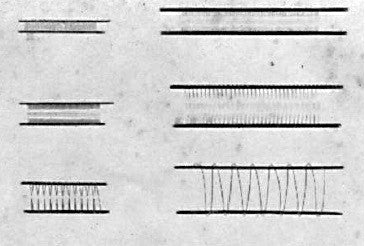
And now we have a very nice little photo which shows from top to bottom the control, screen & supressor grids for, on the left a DF33 and on the right, the much bigger EL37